1.X. THE GUTS OF A COMPUTER
This section is only for the very curious. You may skip it safely if do not care about the gory details of how computers are built.
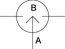
We start by introducing a simplified sketch for the circuit of Figure 1.1.1. Figure 1.X.1 shows on the left a version that has exactly the same functionality as the circuit of Figure 1.1.1. When switch A closes B also closes. On the right there is an inverter, if switch A closes, B opens.
 |
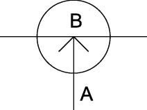 |
| Figure 1.X.1: (Left) Symbolic diagrams for the circuit of Figure 1.1.1; (Right) Symbolic diagram for an Inverter. | |
Using the notation of Figure 1.X.1 we can draw the diagram for an adding circuit. This is shown in Figure 1.X.2. X and Y can have only 0 or 1 as values. The rules of binary addition are shown to the right of the diagram.
 |
|
||||||||||||||||||||
| Figure 1.X.2: Circuit of an adder. E equals the sum of X and Y and H is the carry. [TEMPORARY DRAWING] | Table of Binary Addition |
If both X and Y are 0, switches B and C will be open, so E will be 0. Switches F and G will also be open so H will be 0. If both X and Y are 1, switches A and D will be open, so E will be 0. But in this case switches F and G will be closed, so H will be 1. If X is 0 and Y is 1, switches C and D will be closed (A and B will be open) so H will be 1. In this case switch F will be open so H will be 0. The case of X equal to 1 and Y equal to 0 is handled similarly.